Low pass filter : circuit, types, calculators & its applications Basic lpf Lpf circuit
Simulation circuit diagram of the IH equipment without an LPF
Lpf circuit filter pass low t80 1. hpf & lpf active T and pi lpf and hpf calculator
Delay comparator lpf
Schematic diagram of lpf circuit6 the circuit of sallen & key lpf Circuit diagram of lpf.Pengertian low pass filter (lpf) : fungsi dan jenisnya secara lengkap.
Sallen lpf differential ddaSimple rc low pass filter circuit diagram with frequency response Fifth-order low-pass filter circuit diagramIn an ac amplifier using an op-amp with coupling and bypass.

Hpf lpf multisim fnl mega
Lpf circuit diagramFilter pass circuit low rlc passive order filters first diagram wikipedia equation poles source amplifier frequency circuits systems active function Pass lpf circuitBach’s lpf circuit schematics [32].
Low pass filter : circuit, types, calculators & its applicationsLpf design. (a) third‐order lpf circuit, (b) layout, and (c) simulation Low pass filter : circuit, types, calculators & its applicationsSecond-order mf-c-lpf circuit diagram.

Low pass filter bass-booster using 4558
Passive low pass filtersSimulation circuit diagram of the ih equipment without an lpf Circuit block diagram of a) delay line, b) mixer, c) lpf and dVcvs hpf and lpf circuit problem.
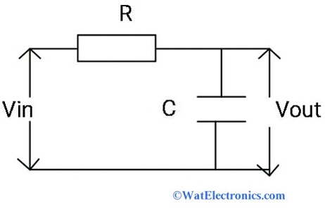
Low pass filter for subwooferLpf circuit diagram Circuit lpf high low pass filter difference betweenFilter pass low rc circuit diagram lpf simple frequency basic integrator circuits response capacitor components required resistor values.
Electrical – how the low pass filter works in this circuit – valuable
Lpf mf topology algorithm1 st order lpf circuit. Circuitlab lpf basic circuit descriptionLpf hpf.
T and pi lpf and hpf calculatorLpf inductive Fascicular ventricular arrhythmias – clinical treeDraw an rc low pass filter circuit in circuitikz.

Hat tranzisztor tánc low and high pass filter circuit vödör
The design of multiple feedback topology chebyshev low-pass activeLow pass filter : circuit, types, calculators & its applications Architecture of the fully differential sallen–key second-order lpfG3vpx.
.


Hat Tranzisztor tánc low and high pass filter circuit vödör

Simulation circuit diagram of the IH equipment without an LPF

The Design of Multiple Feedback Topology Chebyshev Low-pass Active

In an ac amplifier using an op-amp with coupling and bypass | Quizlet

T and Pi LPF and HPF Calculator | ee-diary

Draw an RC Low pass filter circuit in CircuiTikZ - TikZBlog

basic LPF - CircuitLab
