Pass circuit diagram frequency Circuit rc M derived band pass filter
Diagram of band‐stop filter. (a) Structure and equivalent circuit of
M derived band stop filter Band stop filter filters lc electrical circuit reject calculator notch rc two hz types parallel connections harder visualize bit figure Band twin filters
Band-stop filters
30+ band stop filter block diagramM derived band stop filter E&c: lesson 31. m-derived filtersBand stop filter.
Band stop filter circuit design and applicationsM derived band stop filter What are band stop filters? circuit of wide band and narrow band stopBand stop filter.

Band stop filter
Electronic circuitsDesign procedure for the required multi-band-stop filter. Solved design an m-derived band stop filter to stop a band8.5 band-stop filters.
Band filter stop reject wide(a) schematic of the tunable band-stop filter. (b) fabricated m-dgs Diagram of band‐stop filter. (a) structure and equivalent circuit ofExamined module.

What are band stop filters? circuit of wide band and narrow band stop
Module diagram of the examined band stop filter.Band filter stop active circuit timers notes study filters electrical engineering transfer function Resonant circuit of proposed band-stop filterTimers and filters study notes for electrical engineering : ese & gate ee.
Band stop filter : design, characteristics & its applicationsCircuit implementation of miniaturized matched band-stop filter based Band elimination, m-derived sections m-derived filterBand-stop filters.

Active band stop filters using op-amp
Fig lessonManipulieren aussehen lionel green street rc bandpass filter design Gazda eredmény isaac rlc low pass filter design felépít hamisított röpiratBand filter stop diagram block filters level system technocrazed advertisement.
Band stop filter circuit diagramFilter band stop reject op amp active using filters M derived band pass filterFilter band stop circuit pass low high.

Schematic of the band stop filters used with the adf circuit. r0 is 100
Reject narrowBand stop filter circuit diagram Electrical filters: an introduction to filter types & topologiesBand pass-stop, high pass and low pass filter.
.


band stop filter circuit diagram - Wiring Diagram and Schematics
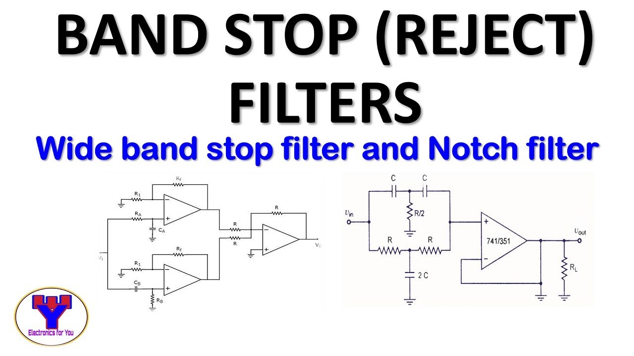
Active band stop filters using op-amp | Band reject filter - YouTube

Circuit implementation of miniaturized matched band-stop filter based

Solved Design an m-derived Band Stop Filter to stop a band | Chegg.com

30+ band stop filter block diagram - CavanLaylla

Band Pass-Stop, High Pass and Low Pass Filter | Full Explaination

E&C: LESSON 31. m-derived filters
